How to configure Hikvision Lift Interface - Part 1 Video.
How to configure Hikvision Lift Interface - Part 2 Video. (setting Lift Interface to Hikvision Intercom System)
Preparation - For the purpose of this document, the following products were used:
1. Latest iVMS-4200 version (V3.1 and up)
Download link: https://www.hikvision.com/au-en/Support/Downloads/Client-Software
2. 1 master lift control and 1 distributed lift control: DS-K2210,DS-K2M0016A
3. 1 GEN 2 door station and 1 indoor station.
4. 1 HIKVISION card reader connecting to the master lift control via Wiegand or RS485(only when you need card reader in the system)
5. Set up the indoor station to connect to the door station
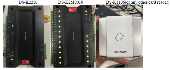
DS-K2210 DS-K2M0016 DS-K1106(or any other card reader)
Indoor station Door station

1. DIP Switch configuration
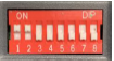
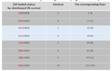
1) The DIP switch of the card reader should be decimal 1 or 2. (E.g. 10000000)
The DIP switch of the main lift controller (DS-K2210) could be 00000000
The DIP switch of distributed lift controller (DS-K2M0016A) is decimal 3-10.
All devices use binary dialing codes. (E.g. 11000000)
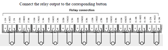
2. Wiring
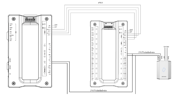
1) Master lift control RS-485 A+ connects to distributed lift control RS-485 A+ as well as card reader RS485A
Master lift control RS-485 A- connects to distributed lift control RS-485 A- as well as card reader RS485B
Master lift control LC_NC connects to distributed lift control LC_NC
Master lift control LC_COM connects to distributed lift control LC_COM
Master lift control LC_NO connects to distributed lift control LC_NO
Master lift control LC_COM2 connects to distributed lift control LC_COM2
3. Configuration
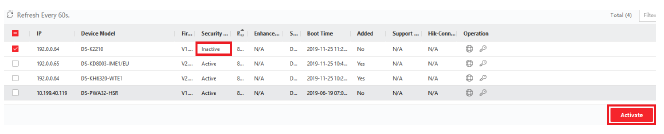
1) Open iVMS-4200 and activate lift controller in “Device Management”
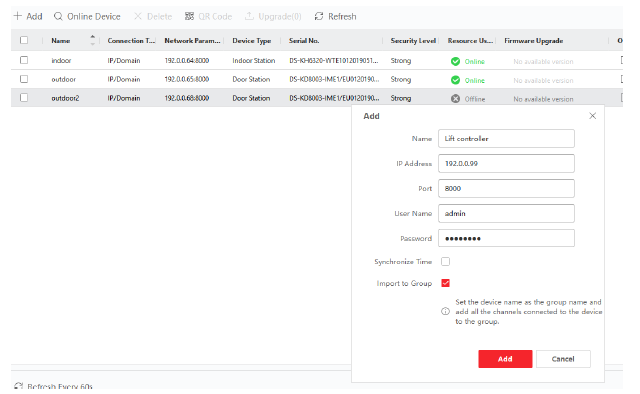
2) Add the lift controller to client.
3) Click remote configuration of the door station and set up the lift control for the door station.
Lift NO”1”. If there is more than 1 master lift control in the system, we need to distribute different lift NO to different master lift control. One door station can add up to 4 master lift control
Lift control type “DS-K2210”
Interface type “Network Interface”
Enable or not ”Yes”
Server IP address is the IP address of the master lift controller. Server port should be 8000.
User name “admin”
Password is the one you used for activating the lift control
Save once done
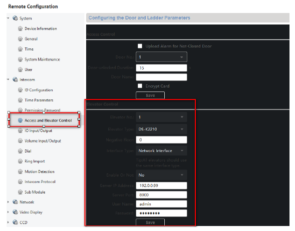
4) Setup an indoor station to connect to the door station
5) Click remote configuration of the indoor station. Setup the floor NO for the indoor station (the example below is shown as NO 2)
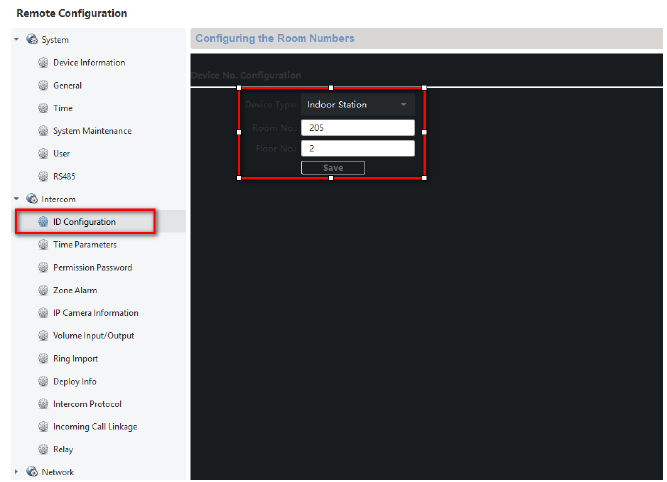
6) Now when you unlock the door from the indoor station, it will trigger relay output 2 in the distributed lift control
Set up the activation time for each relay output of the distributed lift control.
1) We need to setup the activation time for each relay output of the distributed lift control. Click “Access Control” tab in iVMS-4200
Click “Advanced Function”, device parameters, and choose the lift controller.
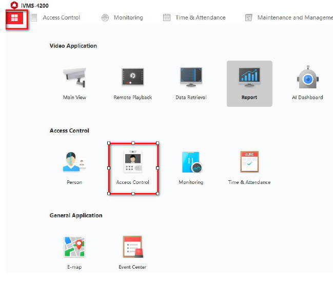
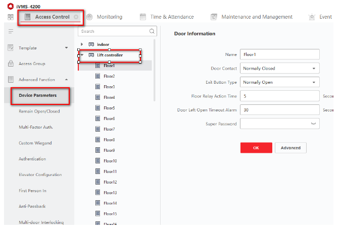
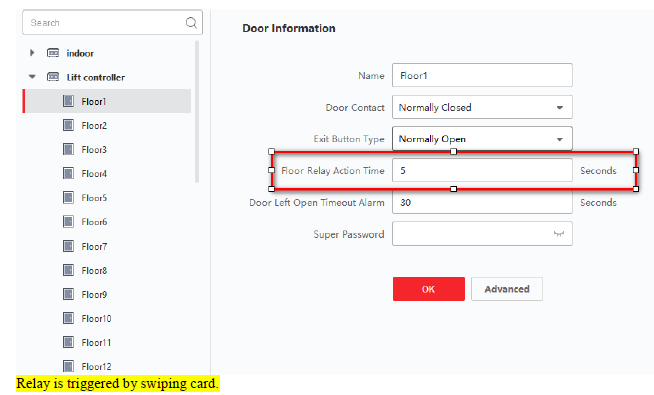
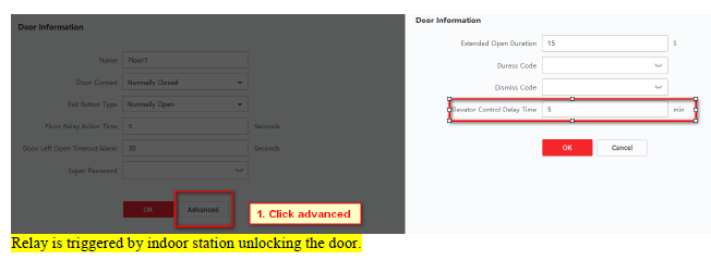
Click any floor under “lift control”. Floor 1 used as an example below
If the master lift control is using firmware V1.0.0, then the floor relay action time is the relay output activation time
If the master lift control is using firmwareV1.0.1, then the lift control delay time is the relay output activation time
5. Enroll users to the system
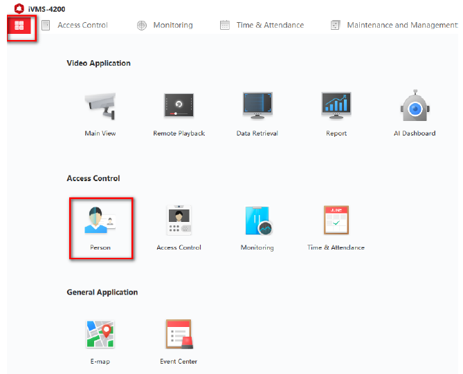
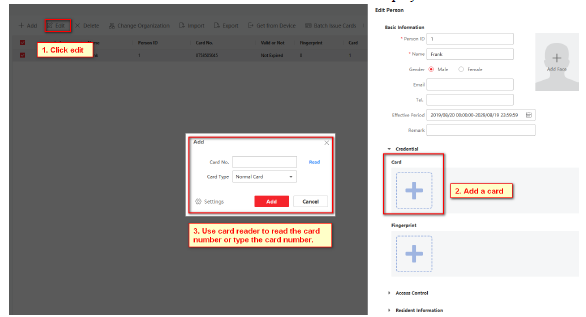
1) Click the “Person” tab in iVMS-4200
Add an organization first, add a user and input user information.
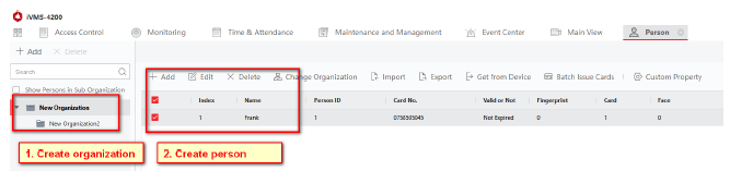
Select a card reader which is connected to the master lift control. Now select “Read” to read the card number and save the information after the card details are displayed
Go to the “Resident Information’ and link on indoor station. And click ‘ Apply Now
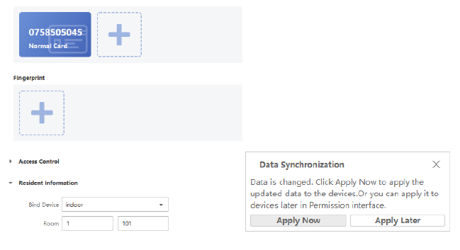
Now when you badge the card in the card reader which is connected to the lift controller, it will trigger the related relay output on distributed lift controller

Installation
1) Controller installation diagram
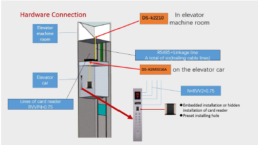
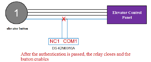
Principle:
(The DIP switch of distributed lift controller (DS-K2M0016A) is decimal 3-10):We control the buttons in the lift, by connecting NC (normally closed) and COM (common) into the button circuit. If the permission is verified, the relay will action and you can press the corresponding level button. The reason for connecting normally closed is that in the normal state the relay coil is energized and the relay contact are open. When the relay output is triggered, the relay contacts will close and allow the relevant button to be pressed. The advantage of this circuit is that it will allow the button to be pressed if the power supply fails and is unable to power the relay coil.